- Trapezoidal Machine
- Corrugated Machine
- Glazed Tile Machine
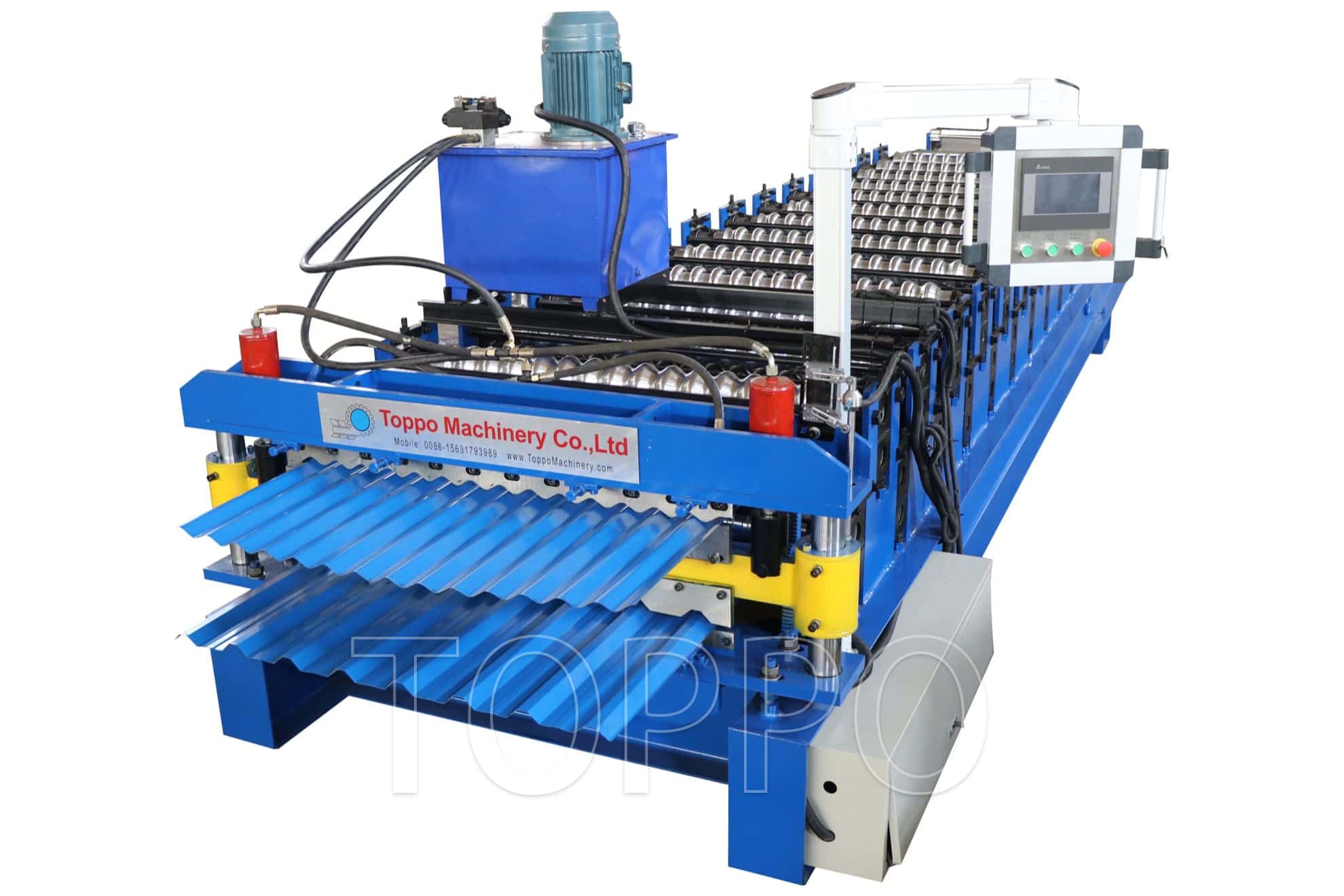
- Double Layer Machine
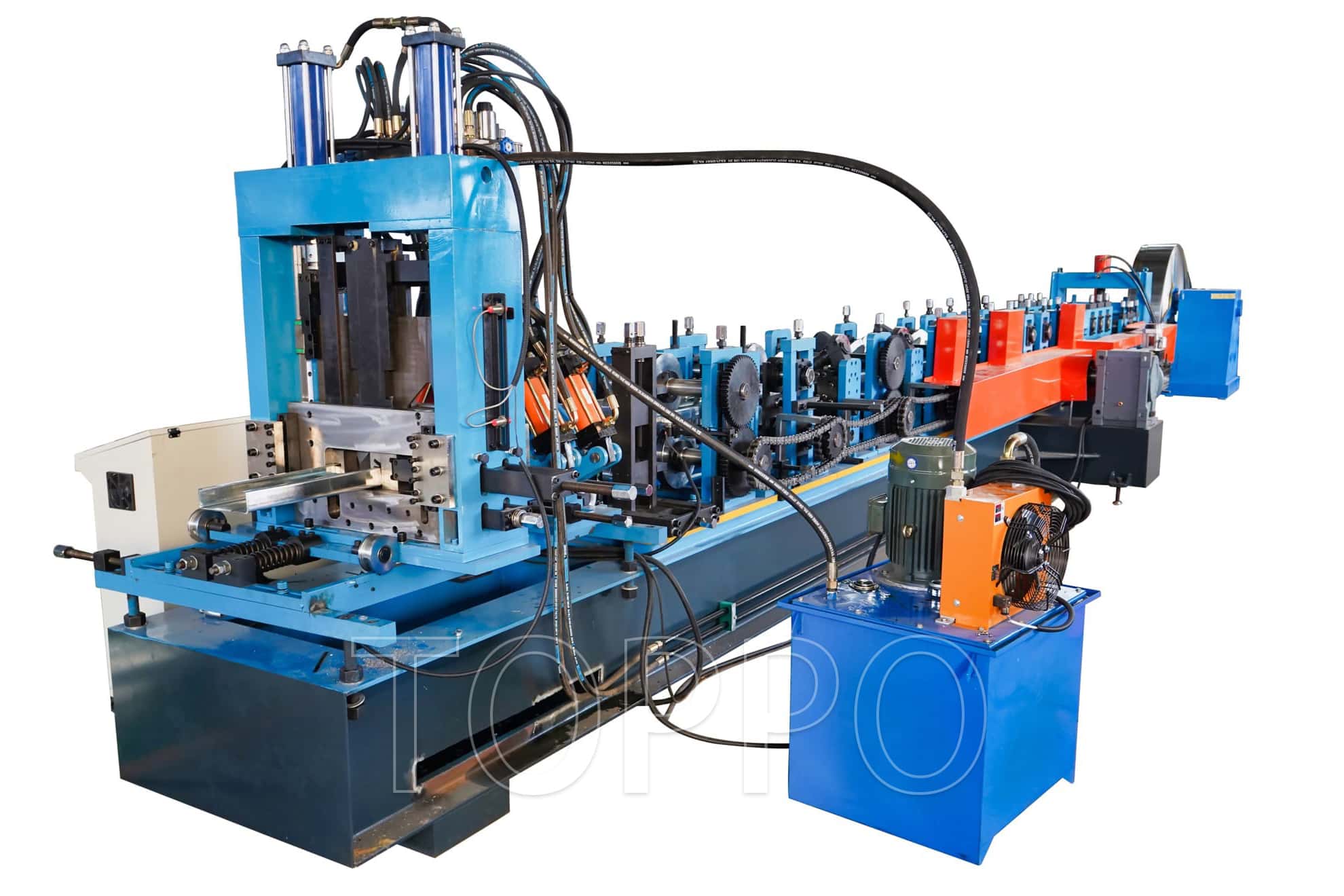
- CZU Purlin Machine
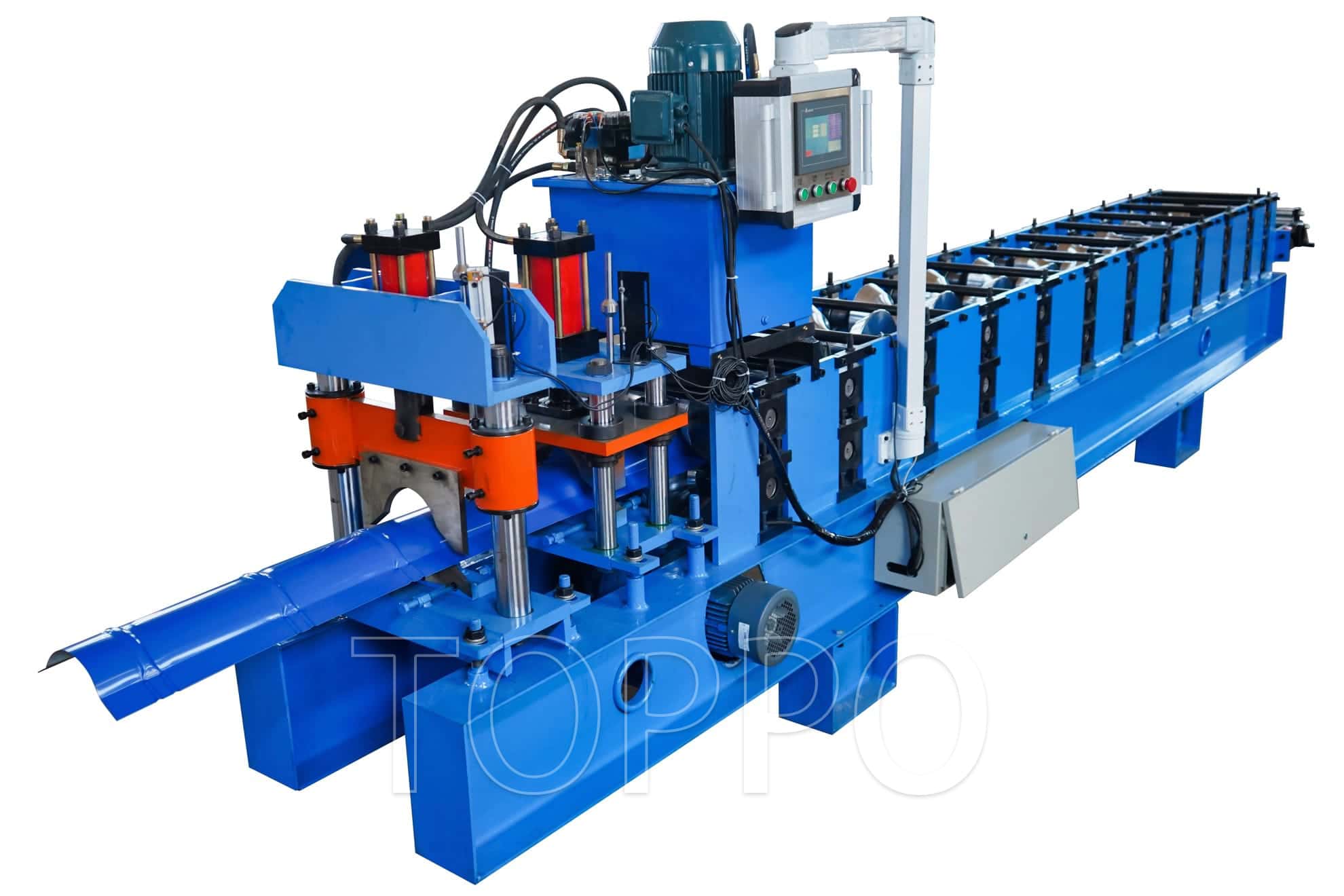
- Ridge Cap Machine
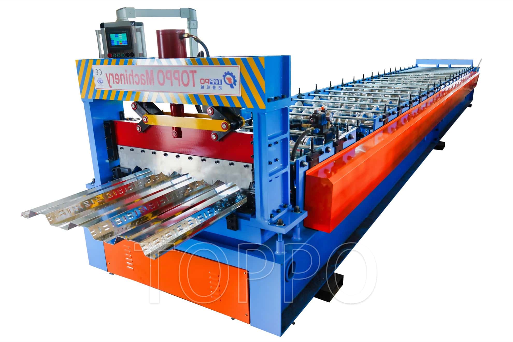
- Floor Decking Machine
- Rolling Door Machine
- Fence Machine
- Embossing Machine
- Standing Seam Machine
- Cut To Length And Slitting Line
- Guard Rail Machine
- Decoiler And Stacker
- Stud And Track Machine
- Gutter And DownPipe
- Curving Machine
- Cladding Panel Machine
- Corollary Equipment



- Trapezoidal Machine
- Corrugated Machine
- Glazed Tile Machine
- Double Layer Machine
- CZU Purlin Machine
- Ridge Cap Machine
- Floor Decking Machine
- Rolling Shutter Door Machine
- Palisade Fence Machine
- Embossing Machine
- Standing Seam Machine
- Cut To Length And Slitting Line
- Guard Rail Machine
- Decoiler And Stacker
- Stud And Track Machine
- Gutter And DownPipe
- Curving Machine
- Cladding Panel Machine
- Corollary Equipment
- Other
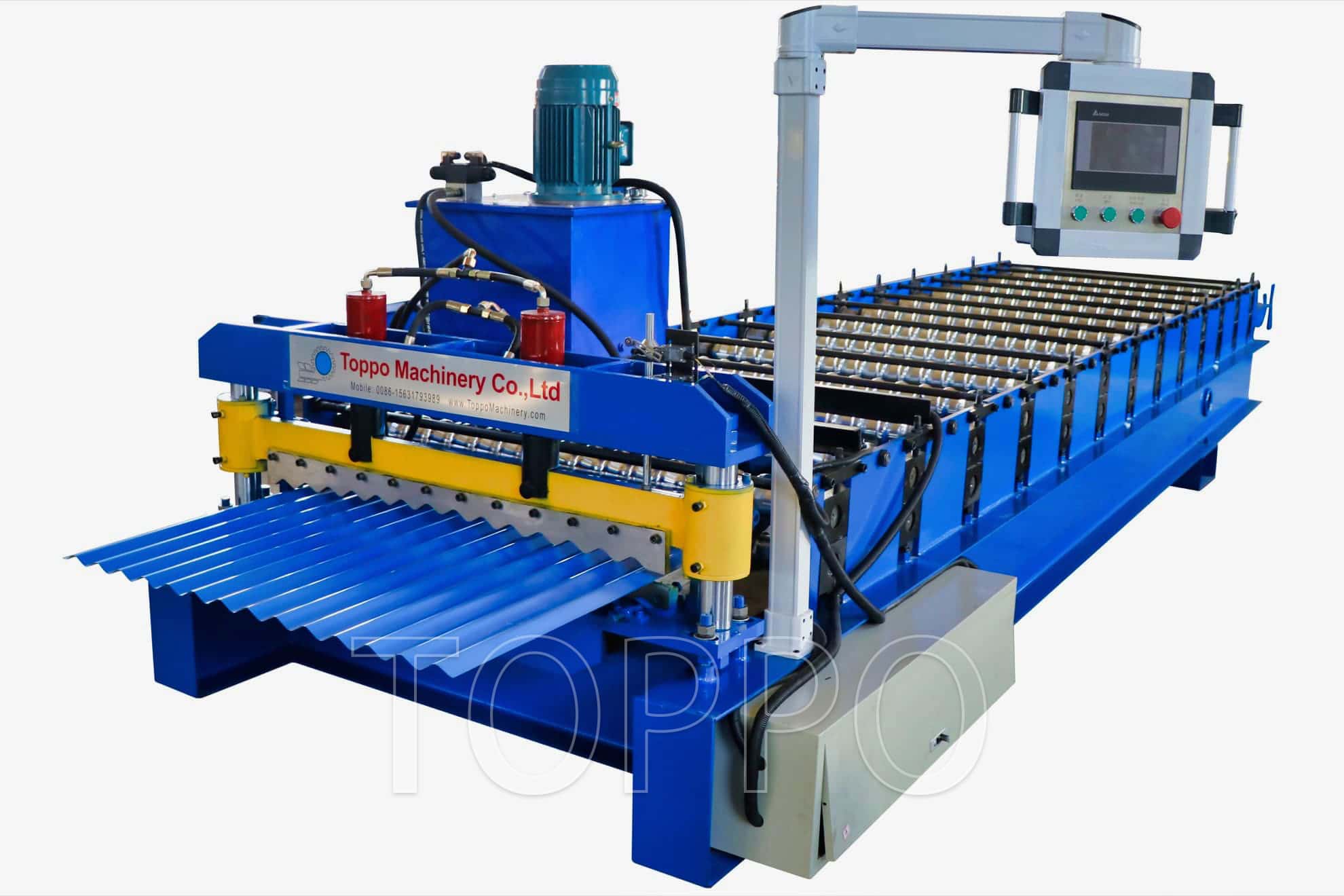
Gear-Driven Corrugated Roofing Sheet Roll Forming Machine
This industrial corrugated roll forming machine is designed for manufacturing metal roofing sheets, wall cladding panels, siding sheets, fencing profiles, and other corrugated construction panels. The machine shown features a rigid welded base, multiple precision forming stations, an upper gearbox drive, a hydraulic profile-cutting section, a compact operator control console, and an enclosed electrical cabinet. The robust drive arrangement is suitable for stable continuous forming and helps transmit forming torque efficiently across the production line.
During operation, coil material is guided into the forming section and gradually shaped through a sequence of matched rollers. An encoder measures the running sheet, while the PLC controls preset length, quantity, batch production, and the hydraulic cutting cycle. The completed panels can be collected on manual receiving tables or transferred through optional conveyors and automatic stacking systems.
Key Product Benefits
Gear-driven forming system: A reduction gearbox and mechanical transmission provide stable torque for continuous panel production.
Automatic PLC control: Panel length, production quantity, batch settings, and operating functions can be managed from the control interface.
Progressive profile forming: Multiple stations gradually shape the corrugation, helping improve dimensional consistency and reduce sudden deformation.
Hydraulic profile cutting: The cutting die is matched to the finished sheet profile for repeatable cuts and clean panel ends.
Heavy-duty structure: A welded frame, reinforced stands, and rigid base help maintain roller alignment during long production runs.
Coated-sheet compatibility: Precision-machined and polished rollers help protect galvanized and pre-painted surfaces.
Custom engineering: Profile shape, station quantity, drive power, thickness range, speed, voltage, and line layout are configurable.
Expandable automation: Hydraulic decoilers, loading cars, leveling units, film devices, conveyors, and stackers can be integrated.
Technical Attributes and Typical Configuration
Note: The values below describe common industrial configurations. Final specifications are confirmed according to the approved profile drawing, material properties, required output, and technical agreement.
| 1. Product Name | Gear-Driven Corrugated Roofing Sheet Roll Forming Machine |
|---|---|
| 2. Machine Category | Automatic cold roll forming production line |
| 3. Main Function | Continuous forming of corrugated roofing and cladding panels |
| 4. Finished Product | Corrugated wave-profile metal sheets |
| 5. Application Fields | Roofing, wall cladding, siding, fencing, and construction panels |
| 6. Suitable Materials | GI, PPGI, GL, PPGL, aluminum, and other cold-formable coils |
| 7. Material Surface | Plain, galvanized, aluminum-zinc coated, or pre-painted |
| 8. Typical Thickness Range | Commonly 0.3-0.8 mm; other ranges available by design |
| 9. Coil Width | Customized according to profile and effective cover width |
| 10. Coil Weight | Matched to selected decoiler capacity |
| 11. Material Yield Strength | Confirmed before roller and drive design |
| 12. Material Tensile Strength | According to customer-supplied coil specification |
| 13. Profile Shape | Round-wave, narrow-wave, or custom corrugated profile |
| 14. Effective Cover Width | Customized from approved drawing |
| 15. Total Sheet Width | Customized |
| 16. Corrugation Pitch | Customized |
| 17. Corrugation Depth | Customized |
| 18. Side-Lap Design | Customized for installation and weather-sealing requirements |
| 19. Forming Method | Continuous progressive multi-pass roll forming |
| 20. Forming Stations | Selected according to profile complexity, material, and thickness |
| 21. Roller Material | High-grade precision-machined steel |
| 22. Roller Heat Treatment | Optional hardening, quenching, chrome plating, or protective treatment |
| 23. Roller Surface Finish | Precision polished to help protect coated sheet surfaces |
| 24. Roller Design | Engineered from the approved profile drawing or physical sample |
| 25. Main Shaft Material | High-strength solid steel |
| 26. Shaft Diameter | Selected according to profile load and machine design |
| 27. Bearing Type | Industrial-duty bearings for continuous operation |
| 28. Forming Stand Structure | Heavy-duty vertical roller stands |
| 29. Main Frame | Rigid welded steel construction |
| 30. Machine Base | Integrated base for alignment and vibration resistance |
| 31. Main Drive | Electric motor with reduction gearbox |
| 32. Transmission Method | Gearbox with shaft, chain, gear, or combined transmission |
| 33. Drive Torque | Selected according to material width, strength, thickness, and speed |
| 34. Main Motor Power | Configured according to production requirements |
| 35. Production Speed | Customized; standard and high-output versions available |
| 36. Speed Control | Frequency-converter or servo-based speed control available |
| 37. Feeding Direction | Left-to-right or right-to-left layout |
| 38. Entry Guide | Adjustable guide assembly for accurate strip alignment |
| 39. Leveling System | Optional pre-leveling or precision leveling device |
| 40. Protective Film Unit | Optional film-covering device for painted material |
| 41. Cutting Method | Hydraulic profile cutting |
| 42. Cutting Position | Post-cut configuration; alternative layouts available |
| 43. Cutting Blade Material | Wear-resistant tool steel matched to the finished profile |
| 44. Cutting Cycle | Automatic hydraulic cutting controlled by PLC |
| 45. Finished Length | Programmable through the control system |
| 46. Length Measurement | Encoder-based automatic measurement |
| 47. Length Calibration | Adjustable through PLC parameters |
| 48. Production Counting | Automatic piece and batch counting |
| 49. Hydraulic Station | Independent hydraulic power unit |
| 50. Hydraulic Motor Power | Selected according to cutting load and line speed |
| 51. Hydraulic Pressure | Adjusted to the final cutter configuration |
| 52. Control System | PLC automatic control |
| 53. Operator Interface | Industrial touch screen or digital control panel |
| 54. Operating Modes | Manual, jog, and automatic modes |
| 55. Control Functions | Length setting, quantity setting, batch control, jog, reset, and status display |
| 56. HMI Language | English or customized language options |
| 57. Electrical Components | Industrial-grade components; preferred brands can be specified |
| 58. Electrical Cabinet | Independent enclosed control cabinet |
| 59. Power Supply | Customized to destination voltage, phase, and frequency |
| 60. Typical Voltage Options | 380V/50Hz/3Ph, 415V/50Hz/3Ph, 440V/60Hz/3Ph, or customized |
| 61. Emergency Stop | Integrated emergency-stop protection |
| 62. Overload Protection | Motor, drive, and electrical overload protection |
| 63. Safety Guarding | Protective covers around transmission and cutting areas |
| 64. Surface Protection | Polished rollers and controlled pressure help protect sheet coatings |
| 65. Forming Stability | Progressive roller design helps reduce distortion and springback |
| 66. Profile Repeatability | Consistent geometry under stable material and setup conditions |
| 67. Machine Color | Standard industrial finish or customized RAL color |
| 68. Overall Dimensions | Determined by profile, station quantity, and auxiliary equipment |
| 69. Machine Weight | Determined by final structure and drive configuration |
| 70. Decoiler Options | Manual, motorized, or hydraulic decoiler |
| 71. Coil Loading Car | Optional hydraulic loading trolley |
| 72. Punching Unit | Optional hydraulic or servo punching system |
| 73. Run-Out Support | Manual receiving tables, conveyor, or automatic stacker |
| 74. Automation Level | Semi-automatic or fully automatic configuration |
| 75. Operator Requirement | Typically one trained operator for automatic production |
| 76. Installation Environment | Indoor industrial workshop with a level foundation |
| 77. Installation Support | Layout, foundation, wiring, setup, and trial-running guidance |
| 78. Commissioning | Remote support or on-site service by agreement |
| 79. Documentation | Operation manual, electrical diagram, layout, and maintenance guide |
| 80. Factory Inspection | Mechanical, hydraulic, electrical, cutting, and profile checks |
| 81. Trial Production | Test run with suitable material before shipment |
| 82. Export Packing | Protective export packing suitable for container transportation |
| 83. Warranty | Manufacturer warranty according to contract terms |
| 84. Spare Parts | Recommended spare-parts package available |
| 85. Customization Scope | Profile, material, thickness, speed, voltage, drive, layout, and control brands |
Standard Production Process
Load the metal coil onto the selected decoiler.
Center the strip through the adjustable entry guide.
Pass the sheet through the optional leveling or protective-film device.
Feed the material into the first roll-forming stations.
Progressively form the required corrugated profile.
Measure the running sheet continuously with the encoder.
Activate hydraulic profile cutting at the programmed length.
Transfer finished panels to receiving tables or an automatic stacker.
Suitable Raw Materials
The machine can be designed for galvanized steel, pre-painted galvanized steel, Galvalume, pre-painted Galvalume, aluminum, and other cold-formable coil materials. Because each material has different yield strength, tensile strength, coating sensitivity, and springback behavior, the roller geometry, station quantity, shaft diameter, gearbox ratio, motor power, and cutting system are finalized after the material specification is confirmed.
Typical Applications
Industrial workshop roofing and wall cladding
Warehouse and logistics-building panels
Agricultural sheds, barns, and livestock buildings
Commercial buildings and light-steel structures
Prefabricated houses and modular buildings
Temporary construction facilities
Metal fencing and protective wall panels
Roofing-sheet manufacturing and distribution centers
Optional Production-Line Equipment
A complete line may include a manual decoiler, motorized decoiler, hydraulic decoiler, coil loading car, leveling unit, protective-film device, pre-punching system, servo feeder, main roll former, hydraulic cutting unit, PLC control cabinet, receiving tables, conveyor, and automatic stacker. The final arrangement can be selected according to coil weight, production target, factory space, labor level, and investment plan.
Information Required for Customization
For an accurate quotation and technical proposal, please provide the finished panel drawing, effective cover width, total sheet width, corrugation pitch, corrugation depth, raw material type, material grade, thickness range, coil width, coil weight, target production speed, required panel length, local voltage, preferred control brands, and required auxiliary equipment. A physical sample may also be used for profile confirmation.
Quality Control and Factory Testing
Before shipment, the machine can be fully assembled, aligned, wired, and test-run. Typical inspection items include roller alignment, gearbox operation, shaft movement, profile dimensions, sheet surface quality, cutting action, length calibration, hydraulic pressure, PLC functions, emergency-stop operation, transmission performance, and overall running stability. Test sheets, photos, and machine-operation videos can be supplied according to the project agreement.
Installation and After-Sales Support
Machine layout drawings, foundation information, electrical diagrams, operation manuals, and maintenance instructions are available. Remote support can assist with machine placement, wiring, hydraulic preparation, parameter setup, length calibration, and trial production. On-site installation, commissioning, and operator training can be arranged according to contract terms.
Maintenance Recommendations
Clean forming rollers and entry guides regularly to protect finished sheet surfaces.
Lubricate gearbox components, bearings, chains, gears, and designated moving parts on schedule.
Inspect roller alignment, transmission tension, coupling condition, fasteners, and cutting-blade clearance.
Check hydraulic oil level, hoses, seals, valves, filters, and operating pressure.
Keep the electrical cabinet dry, clean, and properly ventilated.
Recalibrate length settings after changing material, speed, or encoder components.
Frequently Asked Questions
Q: Can the machine produce our exact corrugated profile?
A: Yes. The forming rollers and cutting blade are designed from the approved drawing or physical sample.
Q: What is the benefit of the gearbox drive?
A: The gearbox provides controlled speed reduction and stable torque transmission, which is useful for continuous roll-forming applications.
Q: Can the line process pre-painted steel?
A: Yes. The forming sequence and roller surface can be optimized for coated material. Material samples are recommended for final testing.
Q: Is the finished panel length adjustable?
A: Yes. Length and quantity can be entered through the PLC control system within the designed range.
Q: Can voltage and control language be customized?
A: Yes. Voltage, phase, frequency, electrical standards, and interface language can be configured for the destination market.
Q: Can an automatic stacker be added?
A: Yes. Receiving tables, conveyors, pneumatic stackers, hydraulic stackers, and servo stacking systems are available.
Why Choose This Gear-Driven Corrugated Roll Former?
This machine combines a robust gearbox-driven structure, progressive roll-forming technology, PLC automation, encoder length control, hydraulic profile cutting, and flexible auxiliary equipment in one production platform. It is suitable for manufacturers seeking stable forming torque, repeatable panel quality, efficient coil processing, reduced manual handling, and a line customized to their roofing profile and material requirements.
- User name Member Level Quantity Specification Purchase Date
- Satisfaction :
-