- Trapezoidal Machine
- Corrugated Machine
- Glazed Tile Machine
- Double Layer Machine
- CZU Purlin Machine
- Ridge Cap Machine
- Floor Decking Machine
- Rolling Door Machine
- Fence Machine
- Embossing Machine
- Standing Seam Machine
- Cut To Length And Slitting Line
- Guard Rail Machine
- Decoiler And Stacker
- Stud And Track Machine
- Gutter And DownPipe
- Curving Machine
- Cladding Panel Machine
- Corollary Equipment
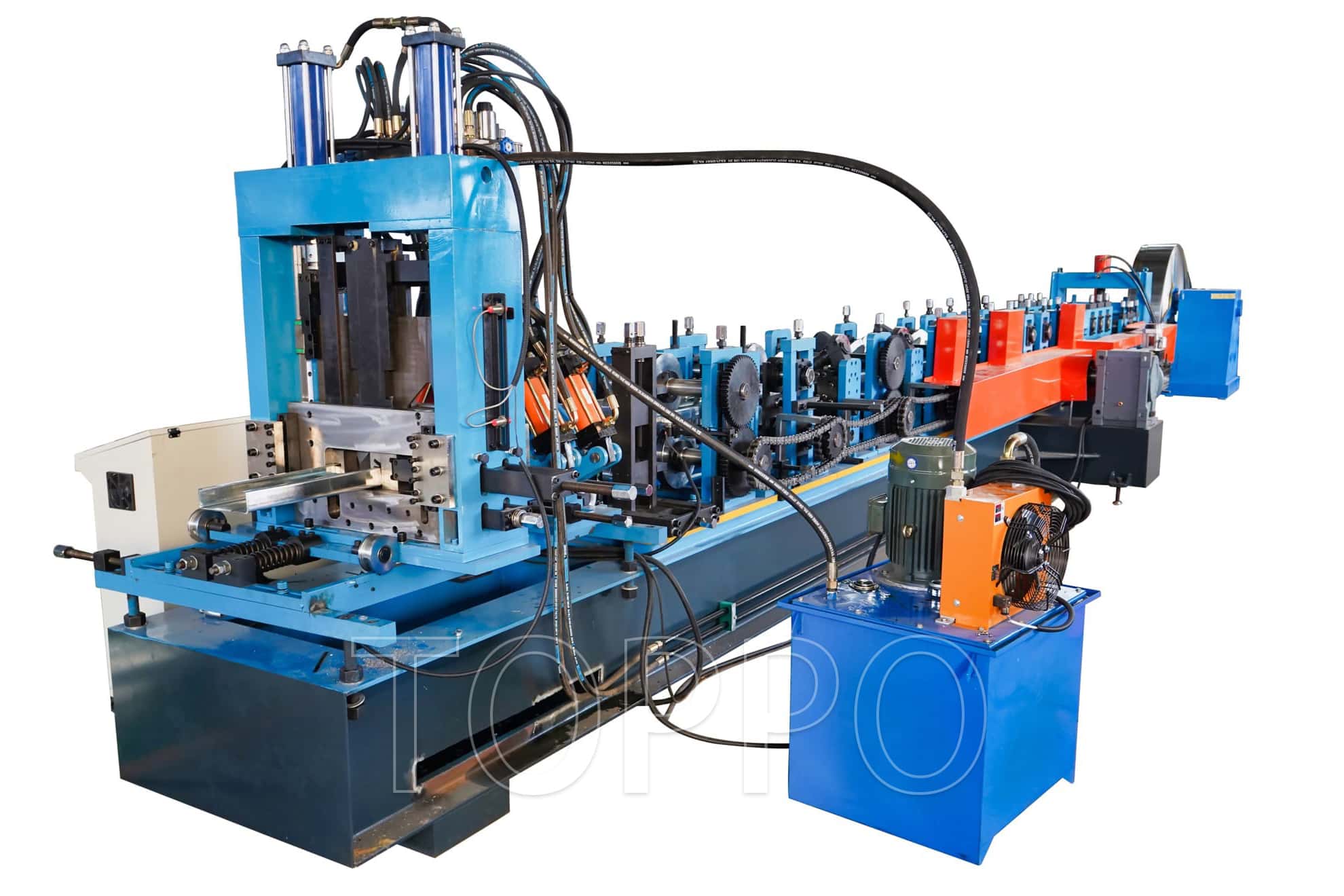



- Trapezoidal Machine
- Corrugated Machine
- Glazed Tile Machine
- Double Layer Machine
- CZU Purlin Machine
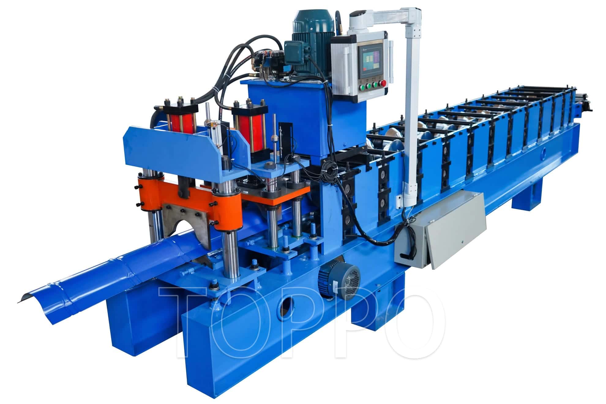
- Ridge Cap Machine
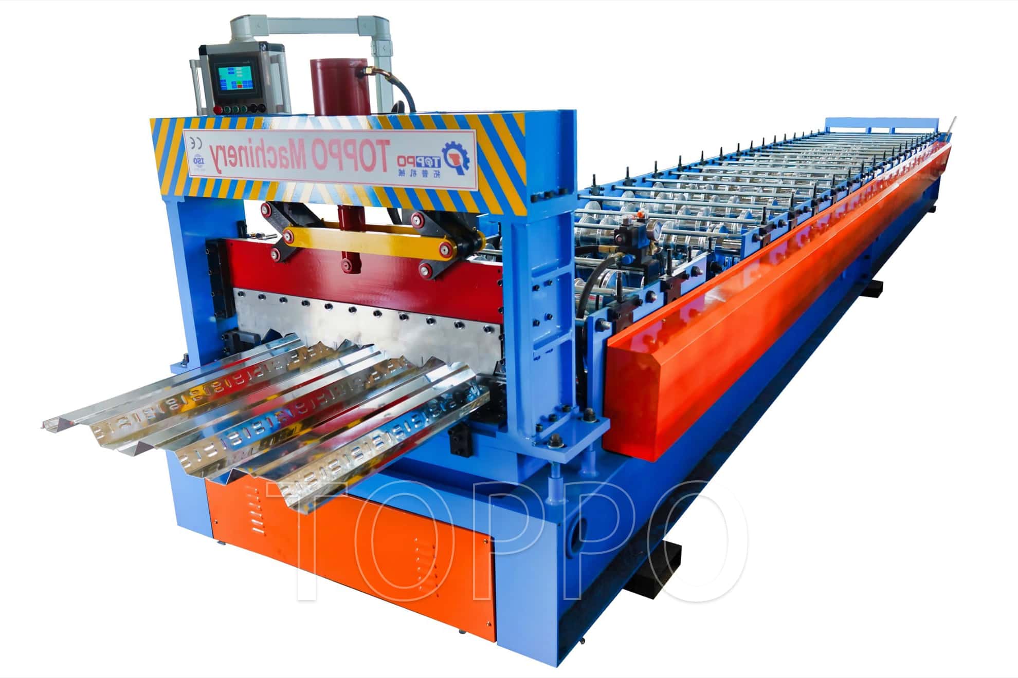
- Floor Decking Machine
- Rolling Shutter Door Machine
- Palisade Fence Machine
- Embossing Machine
- Standing Seam Machine
- Cut To Length And Slitting Line
- Guard Rail Machine
- Decoiler And Stacker
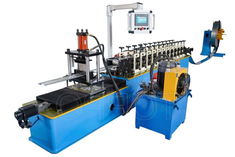
- Stud And Track Machine
- Gutter And DownPipe
- Curving Machine
- Cladding Panel Machine
- Corollary Equipment
- Other
Hydraulic Cut Trapezoidal Roof Panel Roll Forming Machine
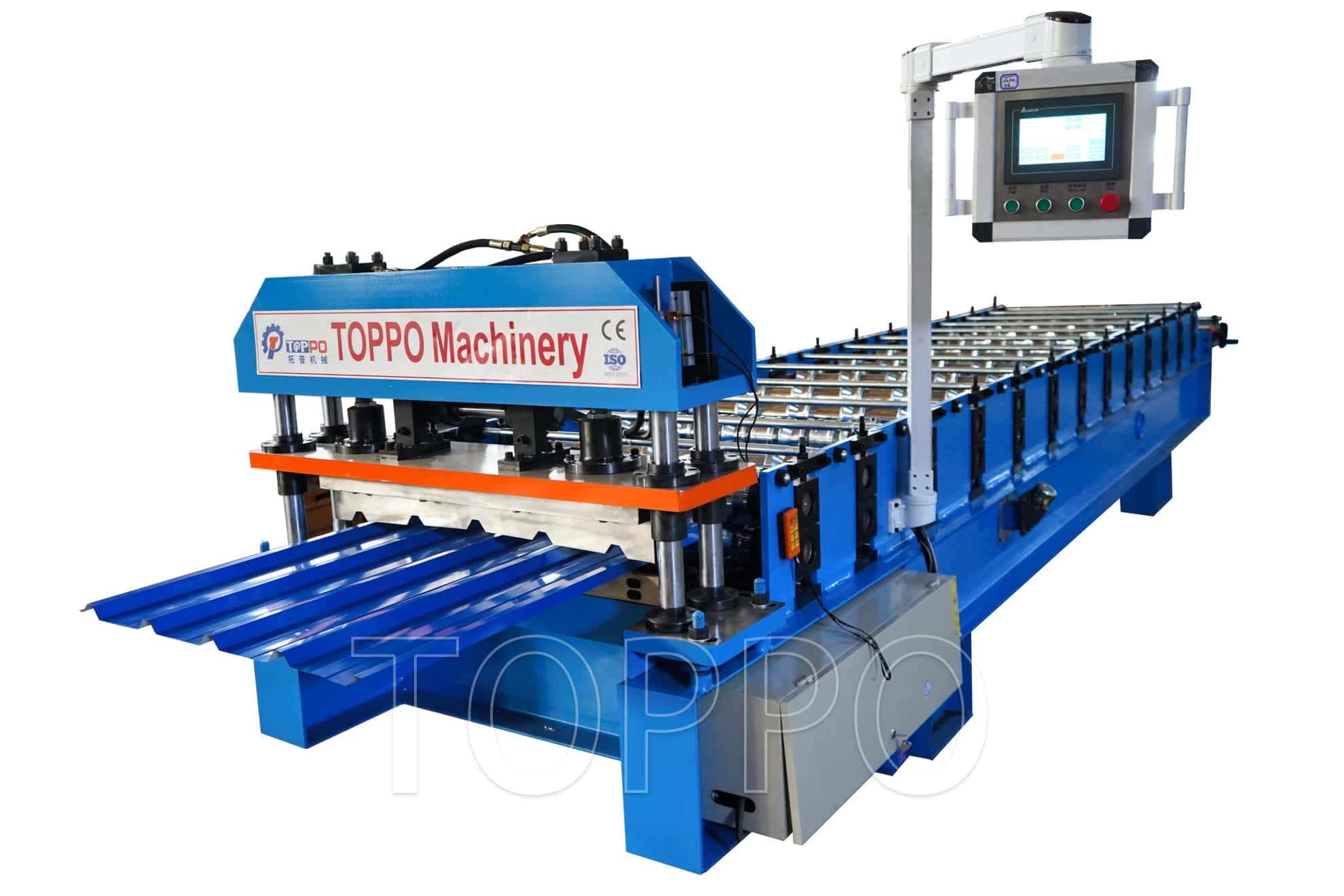
This automatic trapezoidal roof panel roll forming machine continuously converts flat metal coil into durable roofing and wall-cladding sheets. The material enters through an adjustable guiding section and passes through a sequence of precision forming stations. Each pass gradually creates the required ribs, valleys, overlap edges and trapezoidal geometry while helping protect coated surfaces.
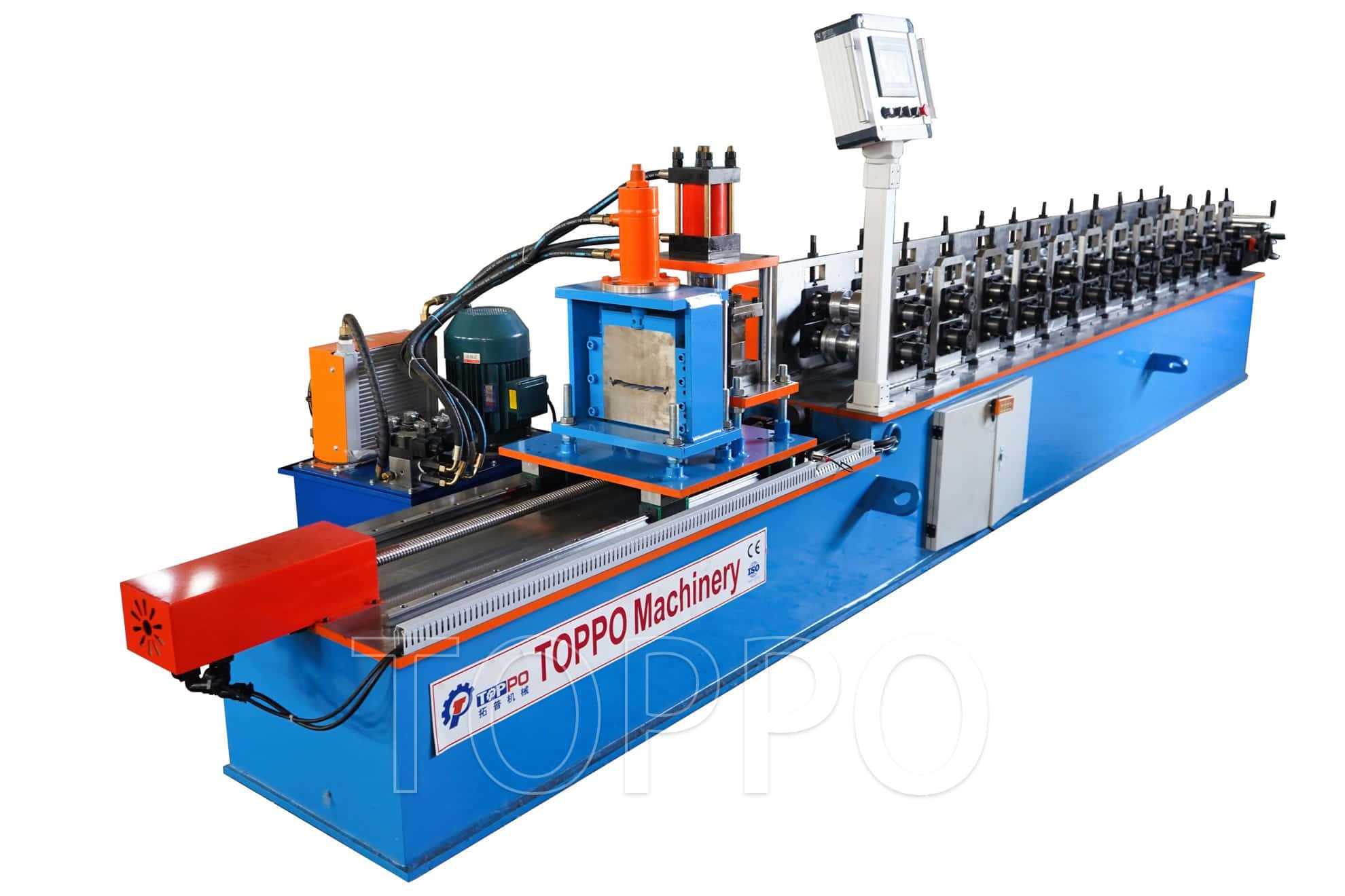
The machine shown is equipped with a heavy welded base, a long forming bed, a four-column hydraulic cutting assembly, an independent hydraulic power station and a swing-arm PLC touch-screen console. The layout provides convenient operation, clear process visibility and dependable production for roofing-sheet factories, steel-structure manufacturers, construction-material suppliers and prefabricated-building companies.
Key Features and Benefits
Automatic production from coil feeding to fixed-length panel cutting.
Swing-arm touch screen can be positioned for convenient operator access.
PLC control supports programmable length, quantity and batch production.
Progressive forming passes help maintain consistent ribs and panel width.
Encoder measurement provides repeatable cutting-length control.
Hydraulic post-cutting offers stable shearing force and clean panel ends.
Reinforced frame and base reduce vibration during continuous operation.
Precision rollers are suitable for galvanized and pre-painted materials.
Profile tooling can be customized from a drawing, sample or local standard.
Optional decoiler, loading car, run-out table, stacker and safety guarding are available.
Typical Technical Attributes and Customizable Specifications
Specification notice: The values below are common reference configurations. Final technical data is confirmed according to the panel drawing, steel grade, material thickness, coil width, production speed and selected auxiliary equipment.
| No. | Attribute | Typical / Customizable Specification |
|---|---|---|
| 1 | Product Name | Trapezoidal roof panel roll forming machine |
| 2 | Machine Type | Automatic cold roll forming production line |
| 3 | Finished Product | Trapezoidal roofing sheet and wall cladding panel |
| 4 | Main Function | Continuous forming, length measuring and automatic cutting |
| 5 | Forming Technology | Progressive multi-pass cold roll forming |
| 6 | Applicable Materials | GI, PPGI, PPGL, Galvalume and aluminum coil |
| 7 | Typical Material Thickness | 0.30-0.80 mm; customized ranges available |
| 8 | Material Yield Strength | Typically 230-550 MPa, design dependent |
| 9 | Common Feeding Width | 914, 1000, 1200, 1220 or 1250 mm |
| 10 | Effective Cover Width | Customized according to profile drawing |
| 11 | Profile Rib Height | Customized according to roofing requirements |
| 12 | Profile Rib Pitch | Customized for the required trapezoidal design |
| 13 | Side-Lap Design | Standard overlap or anti-capillary groove optional |
| 14 | Panel Length | Programmable through PLC |
| 15 | Standard Forming Speed | Approximately 10-25 m/min, excluding stop cutting |
| 16 | High-Speed Option | Servo tracking cutter or flying shear available |
| 17 | Forming Stations | Typically 14-22 stations, profile dependent |
| 18 | Roller Pass Design | Gradual deformation sequence for stable profile development |
| 19 | Roller Material | 45# steel or GCr15 bearing steel |
| 20 | Roller Heat Treatment | Quenched or hardened as required |
| 21 | Roller Surface Treatment | Hard chrome plating and precision polishing |
| 22 | Main Shaft Material | High-strength 45# steel |
| 23 | Main Shaft Diameter | Typically 70-90 mm according to forming load |
| 24 | Forming Stand Type | Wall-plate, guide-post or independent stand structure |
| 25 | Stand Adjustment | Bolted alignment and calibrated roller positioning |
| 26 | Main Frame | Heavy-duty welded steel construction |
| 27 | Machine Base | Reinforced structural steel or H-beam base |
| 28 | Main Drive Type | Chain, gear or gearbox transmission |
| 29 | Main Motor Power | Typically 11-22 kW, configuration dependent |
| 30 | Drive Protection | Optional transmission cover and safety guard |
| 31 | Hydraulic Motor Power | Typically 4-7.5 kW |
| 32 | Hydraulic Working Pressure | Typically 10-16 MPa |
| 33 | Hydraulic Station | Independent power unit with oil tank and valve block |
| 34 | Hydraulic Cooling | Air cooling or oil cooling option |
| 35 | Standard Cutting Method | Hydraulic post-cutting |
| 36 | Cutting Structure | Four-column or guide-post cutting assembly |
| 37 | Optional Cutting Method | Pre-cutting or servo flying shear |
| 38 | Cutting Blade Material | Cr12MoV or equivalent tool steel |
| 39 | Typical Length Accuracy | Within ±1.5 mm after correct calibration |
| 40 | Length Measurement | Rotary encoder measuring system |
| 41 | Control System | PLC automatic control |
| 42 | Operator Interface | Industrial color touch screen |
| 43 | HMI Mounting | Movable swing-arm console |
| 44 | Operation Modes | Automatic, manual and commissioning modes |
| 45 | Length Setting | Digital input through HMI |
| 46 | Quantity Setting | Preset piece quantity and batch quantity |
| 47 | Production Counter | Automatic finished-piece counting |
| 48 | Automatic Stop Function | Stops after completing the programmed batch |
| 49 | Alarm Display | Machine status and fault indication on HMI |
| 50 | Emergency Stop | Installed at the main control position |
| 51 | Standard Voltage | 380 V, 50 Hz, 3 phase |
| 52 | Customized Voltage | 220/380/400/415/440/480 V, 50 or 60 Hz |
| 53 | Electrical Components | Factory standard or customer-specified brands |
| 54 | HMI Language | English or customized multilingual interface |
| 55 | Feeding Guide | Adjustable left-right strip alignment device |
| 56 | Entry Leveler | Optional leveling or straightening unit |
| 57 | Decoiler Type | Manual, electric or hydraulic decoiler |
| 58 | Decoiler Capacity | Typically 3, 5, 8 or 10 tons |
| 59 | Coil Inner Diameter | Typically 450-550 mm |
| 60 | Coil Expansion Method | Manual or hydraulic expansion |
| 61 | Coil Loading Car | Optional for heavy-coil handling |
| 62 | Output Support | Manual run-out table or powered conveyor |
| 63 | Automatic Stacker | Optional pneumatic or servo stacking system |
| 64 | Protective Film Unit | Optional for pre-painted and coated sheet |
| 65 | Punching Function | Optional hydraulic or servo punching station |
| 66 | Lubrication Method | Manual, centralized or automatic lubrication |
| 67 | Safety Guarding | Optional covers, fences and light curtains |
| 68 | Machine Color | Factory standard or customized RAL color |
| 69 | Typical Line Length | Approximately 9-14 m, configuration dependent |
| 70 | Typical Machine Weight | Approximately 8-16 tons, structure dependent |
| 71 | Operator Requirement | Usually 1-2 trained operators |
| 72 | Installation Surface | Level industrial concrete floor |
| 73 | Recommended Environment | Indoor or protected industrial workshop |
| 74 | Profile Design Basis | Customer drawing, sample panel or dimensional data |
| 75 | Surface Protection Design | Roller geometry intended to reduce coating scratches |
| 76 | Panel Flatness Control | Managed through roller alignment and exit support |
| 77 | Factory Trial Run | Mechanical, hydraulic, electrical and sample-forming inspection |
| 78 | Technical Documents | Operation manual, electrical diagram and maintenance guide |
| 79 | Export Packing | Protective film, anti-rust treatment and secured loading |
| 80 | Installation Support | Remote guidance or engineer service by agreement |
| 81 | Operator Training | Operation and maintenance training available |
| 82 | Spare Parts Support | Consumable and critical spare-parts packages available |
| 83 | Applicable Industries | Roofing, wall cladding, steel buildings and prefabricated construction |
| 84 | Customization Scope | Profile, speed, voltage, language, color and auxiliary systems |
Standard Production Line Composition
Decoiler: Supports the coil and releases metal strip into the line.
Feeding and Guiding Unit: Centers the strip and controls entry direction.
Roll Forming Section: Gradually creates ribs, valleys and overlap geometry.
Drive System: Transfers motor power to the forming shafts.
Encoder Measuring Unit: Measures material travel and sends the cutting signal.
Hydraulic Cutting Unit: Cuts each formed panel to the programmed length.
PLC Swing-Arm Console: Controls length, quantity, operating mode and alarms.
Run-Out Table or Stacker: Receives and organizes completed sheets.
Production Workflow
Coil loading → decoiling → strip feeding → alignment → progressive roll forming → encoder measurement → hydraulic cutting → panel discharge → manual collection or automatic stacking.
Typical Applications
The finished trapezoidal panels can be used for industrial workshop roofs, warehouses, logistics centers, agricultural buildings, garages, commercial structures, steel-building enclosures, wall cladding systems, prefabricated houses, temporary buildings and roof-renovation projects.
Custom Profile Engineering
Trapezoidal roofing profiles vary by country and construction standard. The forming rollers and cutting die can be developed from a CAD drawing, dimensioned sketch or physical sample. Important design data includes feeding width, effective cover width, rib height, rib pitch, overlap size, anti-capillary groove, material grade, thickness and coating type.
Available line options include a hydraulic decoiler, coil loading car, entry leveler, pre-cut shear, protective film unit, punching station, servo flying cutter, automatic stacker, safety enclosure, light curtain and remote-monitoring package.
Quality and Process Control
Gradual forming helps reduce sudden deformation and coating damage.
Precision roller and shaft alignment supports consistent rib dimensions.
Adjustable feeding guides reduce lateral strip movement.
A rigid base helps maintain stable forming conditions during long runs.
Matched cutting dies help produce clean ends with limited distortion.
PLC recipe settings simplify repeat orders and standard panel lengths.
Operation and Preventive Maintenance
Inspect bolts, chains, roller alignment, wiring and hydraulic connections before operation.
Keep forming rollers and guides clean to prevent marks on painted surfaces.
Lubricate bearings, chains, gears and sliding components at scheduled intervals.
Calibrate the encoder after installation or whenever length accuracy changes.
Inspect cutting blades regularly and sharpen or replace them when necessary.
Protect the touch screen and electrical components from dust, moisture and impact.
Factory Testing Before Shipment
The line is assembled, aligned and test-run before delivery. Typical inspections include frame level, shaft alignment, roller clearance, transmission operation, hydraulic pressure, electrical functions, emergency stops, encoder measurement, panel dimensions, surface condition and cutting quality. Trial forming can be completed with suitable material when available.
Information Required for an Accurate Quotation
Dimensioned panel profile drawing or physical sample
Raw material type, grade and yield strength
Minimum and maximum material thickness
Coil feeding width and required effective cover width
Required line speed and production target
Coil weight and inner diameter
Destination voltage, frequency and phase
Required decoiler, cutting, stacking and safety options
Frequently Asked Questions
Can the machine produce our local trapezoidal profile?
Yes. The roller tooling and cutting die can be designed according to a dimensioned drawing or physical sample.
Can it process high-strength steel?
Yes. Roller material, shaft diameter, station quantity, motor power and frame structure are selected according to steel grade and thickness.
Can different panel lengths be programmed?
Yes. Operators can enter different lengths and quantities through the PLC touch screen.
Can an automatic stacker be included?
Yes. Manual run-out tables, powered conveyors and automatic stackers are available according to panel length and production speed.
- User name Member Level Quantity Specification Purchase Date
- Satisfaction :
-