- Trapezoidal Machine
- Corrugated Machine
- Glazed Tile Machine
- Double Layer Machine
- CZU Purlin Machine
- Ridge Cap Machine
- Floor Decking Machine
- Rolling Door Machine
- Fence Machine
- Embossing Machine
- Standing Seam Machine
- Cut To Length And Slitting Line
- Guard Rail Machine
- Decoiler And Stacker
- Stud And Track Machine
- Gutter And DownPipe
- Curving Machine
- Cladding Panel Machine
- Corollary Equipment



- Trapezoidal Machine
- Corrugated Machine
- Glazed Tile Machine
- Double Layer Machine
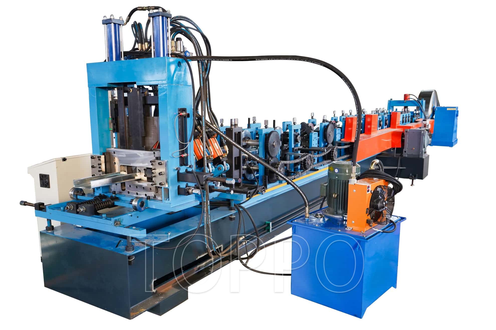
- CZU Purlin Machine
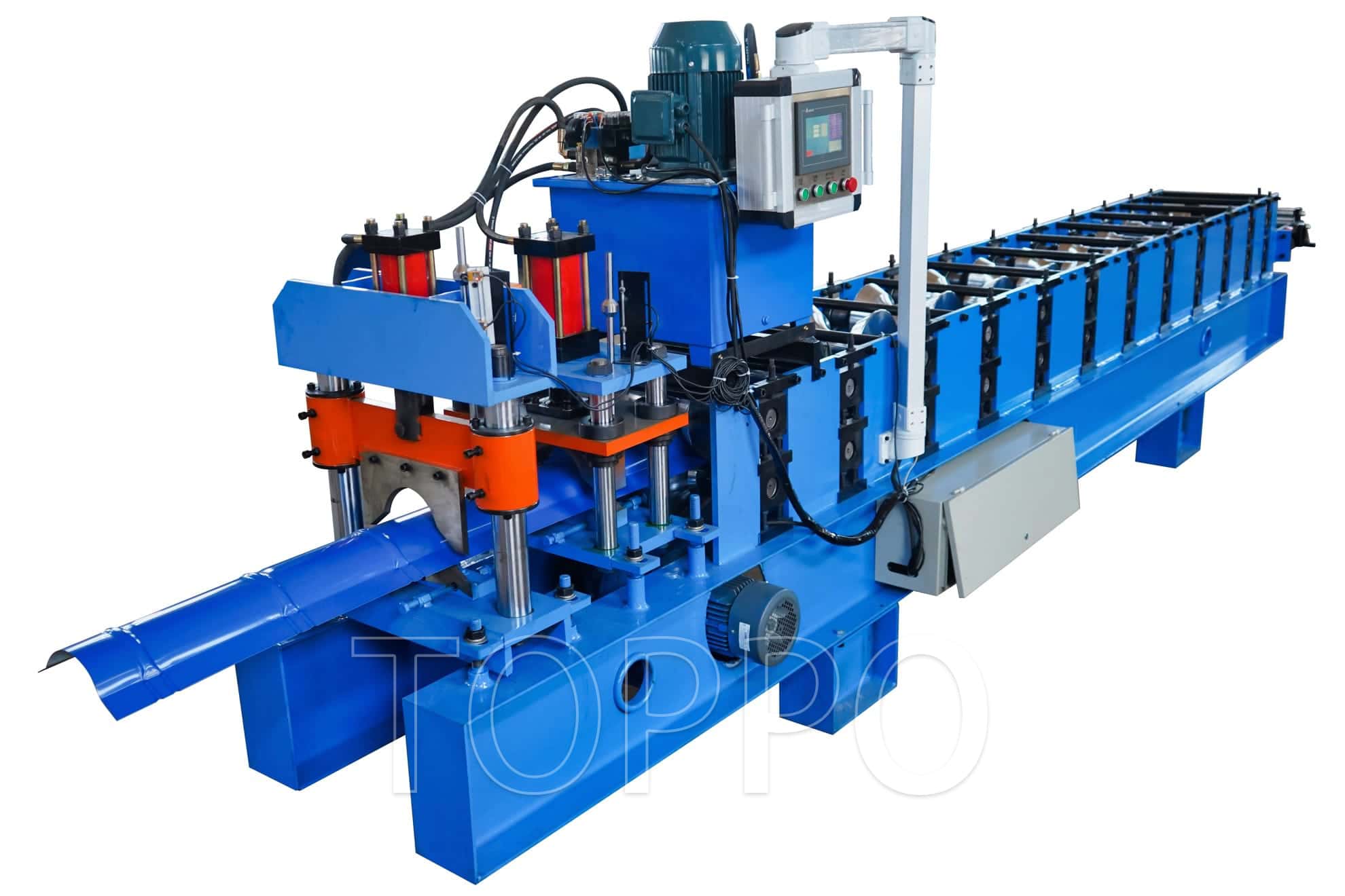
- Ridge Cap Machine
- Floor Decking Machine
- Rolling Shutter Door Machine
- Palisade Fence Machine
- Embossing Machine
- Standing Seam Machine
- Cut To Length And Slitting Line
- Guard Rail Machine
- Decoiler And Stacker
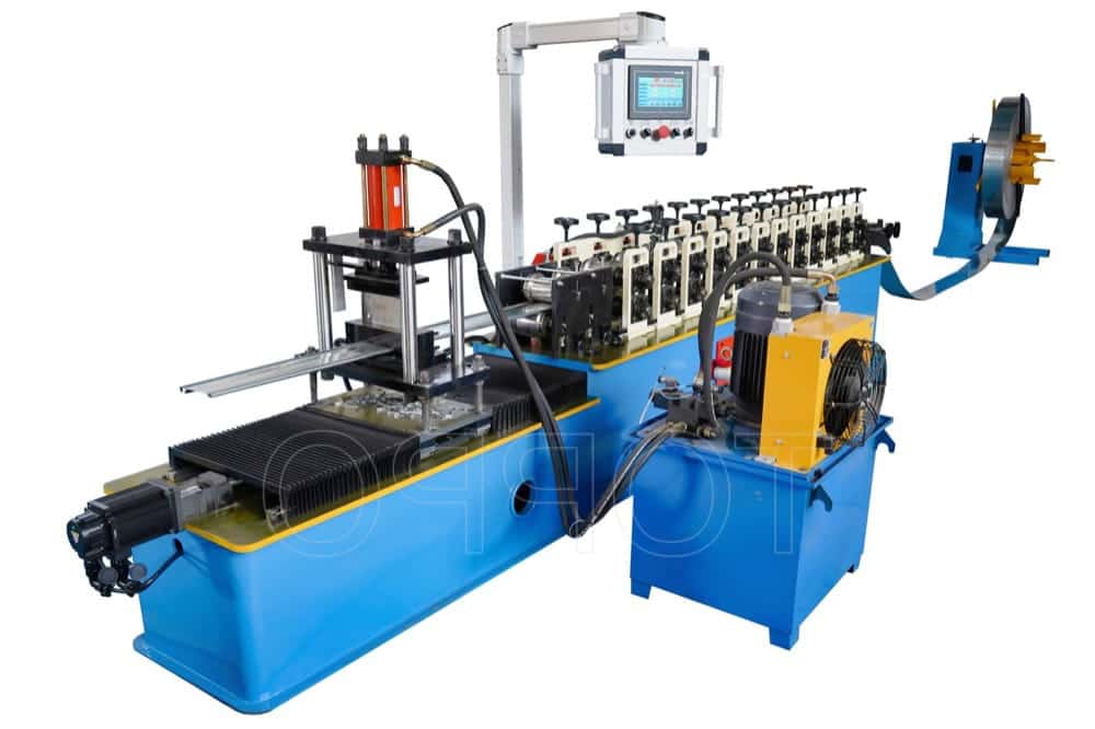
- Stud And Track Machine
- Gutter And DownPipe
- Curving Machine
- Cladding Panel Machine
- Corollary Equipment
- Other
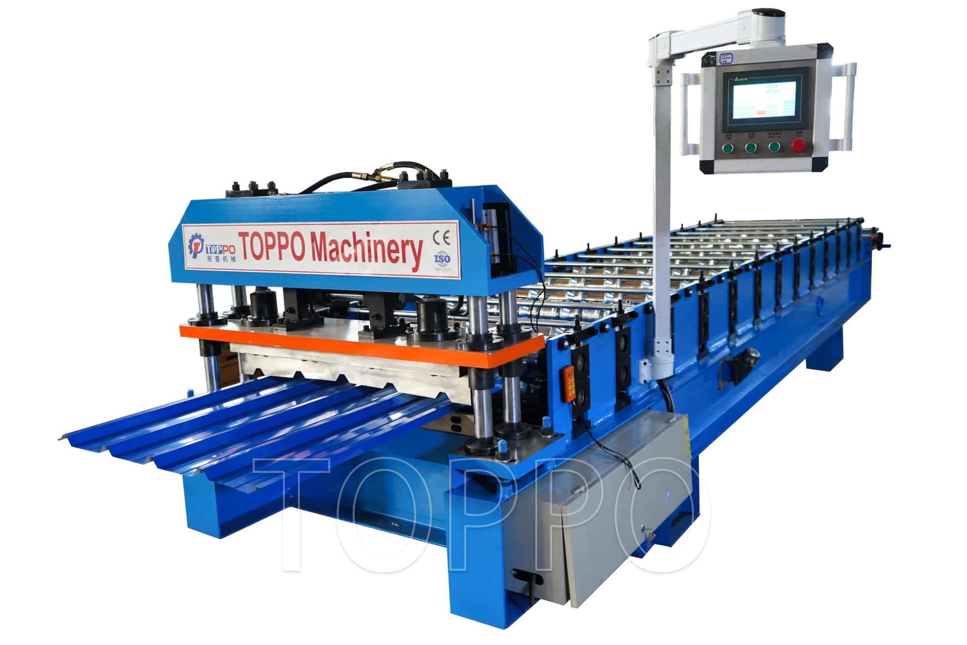
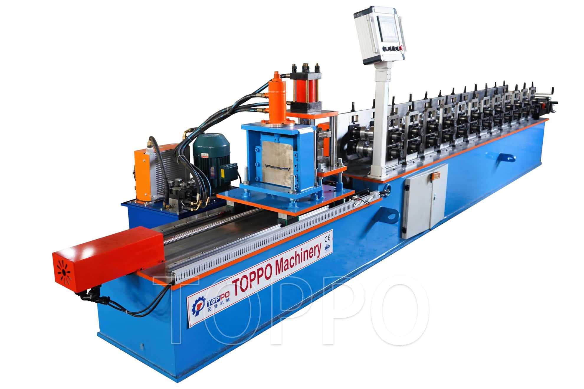
Automatic Trapezoidal Roofing Panel Cold Roll Forming Line
This automatic production line transforms flat metal coil into accurately shaped trapezoidal roofing and wall-cladding panels through a controlled cold roll forming process. It is suitable for manufacturers supplying industrial buildings, warehouses, workshops, agricultural structures, prefabricated houses and commercial construction projects.
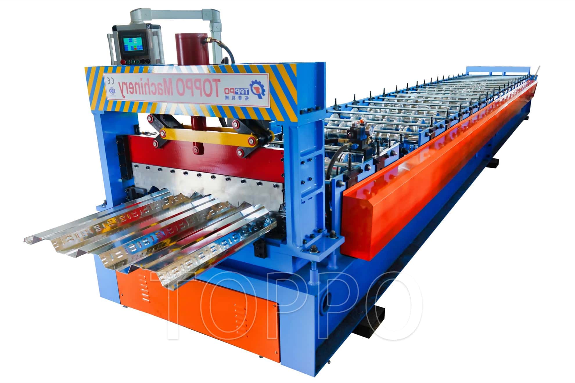
The machine shown is built on a heavy welded steel base and equipped with precision forming stands, a hydraulic cutting unit, an independent hydraulic power station and an elevated operator control console. The gradual forming sequence helps control strip deformation, protect coated surfaces and maintain consistent rib geometry and panel width.
Key Advantages
Automatic production from coil feeding to fixed-length cutting
Stable trapezoidal profile and repeatable panel dimensions
PLC and touchscreen control for length, quantity and production settings
Encoder measuring system for accurate batch production
Heavy-duty structure for continuous industrial operation
Hydraulic profile cutting for clean and consistent panel ends
Custom profile design based on drawing, sample or required cover width
Optional decoiling, leveling, punching, stacking and packaging equipment
Typical Product Attributes and Technical Configuration
Technical note: The following values are common reference configurations. Final specifications are confirmed according to the approved profile drawing, raw-material grade, thickness range, required line speed and local electrical standard.
| Attribute | Typical Specification / Description |
|---|---|
| 1. Product name | Automatic trapezoidal roofing panel cold roll forming line |
| 2. Equipment type | Automatic metal sheet cold roll forming machine |
| 3. Main purpose | Production of trapezoidal roof and wall-cladding sheets |
| 4. Finished profile | Trapezoidal ribbed metal panel |
| 5. Production method | Continuous multi-pass cold roll forming |
| 6. Suitable materials | GI, GL, PPGI, PPGL and aluminum coil |
| 7. Typical sheet thickness | Approximately 0.30-0.80 mm; customized ranges available |
| 8. Material strength | Machine designed according to specified yield and tensile strength |
| 9. Input coil width | Customized according to the finished profile |
| 10. Effective cover width | Manufactured according to the approved panel drawing |
| 11. Rib height | Customized for strength, drainage and appearance |
| 12. Rib pitch | Customized to the selected trapezoidal geometry |
| 13. Side-lap edge | Designed for panel overlap and weather resistance |
| 14. Standard forming speed | Typically 10-25 m/min depending on profile and cutting system |
| 15. High-speed option | Available with upgraded drive and servo flying-cut system |
| 16. Forming stations | Usually 12-20 stations depending on profile complexity |
| 17. Roller material | Precision-machined 45# steel or optional alloy steel |
| 18. Roller treatment | Hard chrome plating, polishing and anti-corrosion protection |
| 19. Roller machining | CNC machined according to the approved forming flower |
| 20. Main shaft material | Heat-treated high-strength steel |
| 21. Typical shaft diameter | Approximately 70-95 mm, selected by forming load |
| 22. Bearing arrangement | Industrial bearing blocks for continuous-duty support |
| 23. Main frame | Heavy-duty welded steel base |
| 24. Frame processing | Stress-relieved, machined and aligned before assembly |
| 25. Forming-stand structure | Steel plate or cast-iron arch configuration |
| 26. Transmission type | Chain, gear or gearbox transmission |
| 27. Main motor power | Typically 5.5-11 kW, matched to speed and material |
| 28. Hydraulic motor power | Typically 4-7.5 kW |
| 29. Hydraulic station | Oil tank, motor, pump, valve block, gauge, filter and cooling option |
| 30. Control system | PLC automatic control |
| 31. Operator interface | Touchscreen HMI or digital control panel |
| 32. Speed regulation | Variable-frequency inverter control |
| 33. Length measurement | Electronic encoder measuring system |
| 34. Length setting | Programmed through the HMI |
| 35. Batch control | Automatic quantity setting and piece counting |
| 36. Operating modes | Automatic, manual and jog modes |
| 37. Cutting method | Hydraulic post-cut, pre-cut or optional tracking cut |
| 38. Cutting blade material | Cr12, Cr12MoV or equivalent hardened tool steel |
| 39. Typical length accuracy | Approximately +/-1.5 mm under normal operating conditions |
| 40. Blade profile | Matched to the finished trapezoidal panel shape |
| 41. Feeding guide | Adjustable side guides for accurate strip centering |
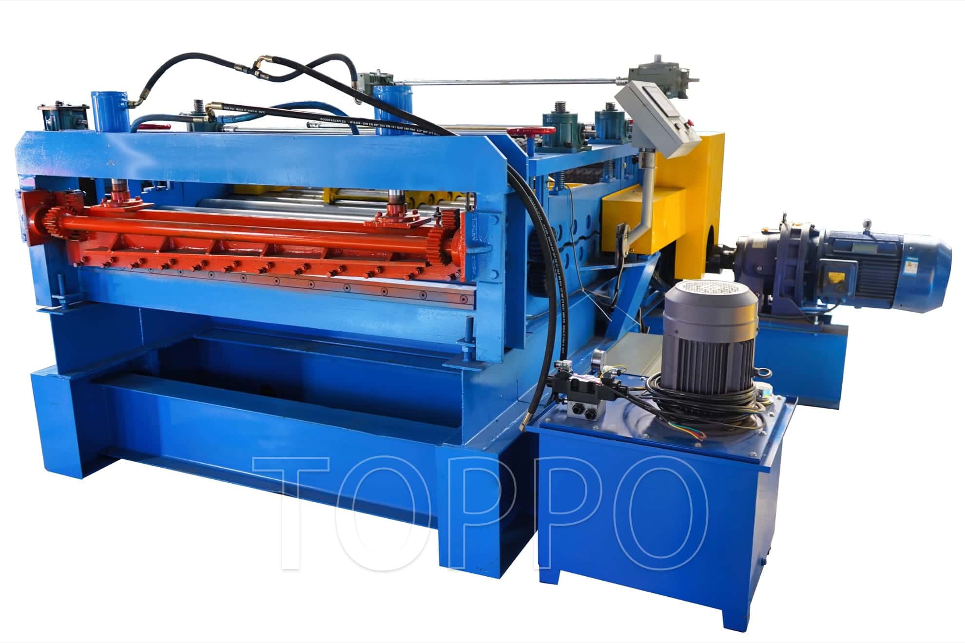
| 42. Entry leveling | Optional multi-roll leveling unit |
| 43. Decoiler type | Manual, hydraulic or automatic loading decoiler |
| 44. Typical decoiler capacity | 3-5 tons; heavier capacities available |
| 45. Coil inner diameter | Typically 450-550 mm or customized |
| 46. Coil outer diameter | Selected according to coil weight and factory layout |
| 47. Coil loading method | Crane-assisted, hydraulic expansion or coil-car loading |
| 48. Output support | Run-out tables or roller conveyor |
| 49. Stacking option | Manual receiving, pneumatic, servo or vacuum stacker |
| 50. Punching option | Optional pre-punching or inline hydraulic punching |
| 51. Marking option | Optional inkjet, laser or embossing system |
| 52. Electrical voltage | 220 V, 380 V, 400 V, 415 V, 440 V or local standard |
| 53. Frequency | 50 Hz or 60 Hz |
| 54. Electrical phase | Three-phase industrial power supply |
| 55. Electrical components | International or customer-specified brands available |
| 56. Emergency protection | Emergency stops and motor overload protection |
| 57. Safety guarding | Protective covers and warning labels around moving sections |
| 58. Lubrication | Accessible lubrication points with optional centralized system |
| 59. Surface finish | Industrial primer and durable topcoat |
| 60. Machine color | TOPPO standard color or buyer-selected color |
| 61. Production direction | Left-to-right or right-to-left arrangement |
| 62. Machine footprint | Determined by forming stations and auxiliary equipment |
| 63. Machine weight | Determined by frame design and final configuration |
| 64. Profile customization | Designed from customer drawing, sample or required cover width |
| 65. Profile-change solution | Spacer, cassette, double-layer or quick-change option |
| 66. Material utilization | Continuous forming helps reduce scrap and improve coil yield |
| 67. Surface protection | Progressive forming helps minimize scratches on coated sheet |
| 68. Noise and vibration control | Rigid base and aligned transmission improve operating stability |
| 69. Quality inspection | Assembly inspection, no-load test and sample-panel trial |
| 70. Documentation | Operation manual, electrical diagram, foundation drawing and maintenance guide |
| 71. Standard accessories | Control cabinet, hydraulic station, tool kit and receiving tables as contracted |
| 72. Spare parts | Recommended wearing parts supplied according to order scope |
| 73. Installation support | Remote guidance or optional on-site commissioning |
| 74. Operator training | Operation, adjustment, maintenance and safety instruction |
| 75. Packaging | Export-standard protective packing for sea or land transport |
| 76. Custom manufacturing | OEM and ODM configurations supported |
Production Process
Coil loading: The raw-material coil is placed on the decoiler and aligned with the line.
Guided feeding: Adjustable entry guides center the strip before it enters the first forming stand.
Progressive forming: Multiple roller stations gradually shape the strip into the required trapezoidal profile.
Length measurement: The encoder continuously measures panel travel and sends data to the PLC.
Hydraulic cutting: The profile-matched cutter operates when the programmed length is reached.
Receiving and stacking: Finished panels are discharged onto support tables or transferred to an optional automatic stacker.
Typical Applications
Finished panels are suitable for industrial workshop roofs, warehouse walls, logistics centers, agricultural sheds, commercial buildings, garages, carports, prefabricated houses, modular buildings, temporary structures and general steel-building projects.
Optional Line Configurations
Manual decoiler, roll former, hydraulic cutter and receiving tables
Hydraulic decoiler with coil car and entry leveling unit
High-speed line with servo tracking or flying-cut technology
Inline punching, marking and production-data recording
Double-layer machine for two profiles on one frame
Automatic stacking, counting, strapping and packaging system
Information Required for Custom Design
Please provide the finished-panel drawing, raw-material type, material grade, thickness range, input coil width, effective cover width, rib height, rib pitch, required forming speed, preferred cutting method, local voltage and desired auxiliary equipment. These details allow the roller design, motor power, shaft loading and control strategy to be matched to the actual production requirement.
Quality Control and Testing
Before shipment, the machine is assembled, aligned and test-run. The forming sequence, shaft alignment, transmission operation, hydraulic pressure, cutting action, PLC program, encoder measurement and sample-panel dimensions are checked against the approved technical specification.
Maintenance Recommendations
Clean forming rollers and remove metal particles after production.
Lubricate bearings, chains, gears and guide components regularly.
Check hydraulic oil level, hoses, filters and pressure settings.
Verify cutting-blade clearance when changing material thickness.
Keep the electrical cabinet clean, dry and well ventilated.
Inspect fasteners, alignment and safety devices periodically.
Service and Support
TOPPO provides remote installation guidance, commissioning assistance, operator training, maintenance recommendations and spare-parts support. Optional on-site engineering service can be arranged according to the destination and contract terms.
- User name Member Level Quantity Specification Purchase Date
- Satisfaction :
-